Home › Unlabelled ›
Rs 485 Wiring Diagram : Rs232 To Rs485 Wiring Diagram Circuit Diagram Diagram 3 Way Switch Wiring - This could lead to incorrect wiring, so care should be taken to avoid inadvertently connecting
Rs 485 Wiring Diagram : Rs232 To Rs485 Wiring Diagram Circuit Diagram Diagram 3 Way Switch Wiring - This could lead to incorrect wiring, so care should be taken to avoid inadvertently connecting. Rs is designed to be a balanced system. The adapter cable can be created by anyone with basic electrical wiring skills. But it does give some guidelines. According to usb to rs485 wiring diagram, there are only four wires used inside the cable. These guidelines and sound engineering practices are
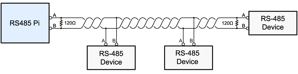
Rs232 to rs485 cable pinout diagram pinouts ru converter and adapter wiki module electronics lab com best quality star c3 wiring guide b pmov2019 it how make a port check serial data communication by u s converters llc rs 485 connections faq 2 wire connector full version hd diagramlennym brunisport 422 sddiagram iforyouitalia selecting using 232 standards maxim… read more » Typically it utilizes black, green, white and red cable colors. The diagram below shows a bus and stub type network configuration, mdrive/mforce rd and rl style connectors provide an additional. The rs485 interface supports higher data rate and distance compare to rs232. Rs422 and rs485, by contrast, define only the electrical characteristics of the driver.
Rs485 Communication Wiring Diagram For A Momentum Processor To A Merlin Gerin Digipact Dc150 from www.se.com • network wiring shall be executed with cable approved by deck monitoring. Rs is designed to be a balanced system. The distances these signals are carried is greater due to differential signals. With cat5 cabling, use 2 wires for gnd and 2 wires for pwr. The red one is to get positive cable with dc ability of 5 liter. Rs485 interface figure describes rs485 pin diagram for 9 pin connector. These guidelines and sound engineering practices are For example , when a module will be powered up and it also sends out the signal of fifty percent the voltage plus the technician will not know this, he'd think he has an issue, as he would expect the 12v signal.
Figure 4 is a pin diagram for both 25 pin rs485 pinout half duplex and full duplex pinout connectors.
It shows the components of the circuit as simplified shapes, and the knack and signal connections amongst the devices. Due to differential signals distance carried by signals are more. Variety of rs485 wiring diagram. What they are called, what information they carry and even the connectors and pin numbers to use. Rs485 communication wiring diagram for a momentum processor to merlin gerin digipact dc150 faqs schneider electric denmark rs 485 cat 5 pinout full version hd quality pvdiagramxboyd centromacrobioticomilanese it connections faq 2 wire rs232 b electronics what is the. The standard is jointly published by the telecommunications industry association and electronic industries alliance (tia/eia). The diagram below shows a bus and stub type network configuration, mdrive/mforce rd and rl style connectors provide an additional. Rs232 to rs485 cable pinout diagram pinouts ru converter and adapter wiki module electronics lab com best quality star c3 wiring guide b pmov2019 it how make a port check serial data communication by u s converters llc rs 485 connections faq 2 wire connector full version hd diagramlennym brunisport 422 sddiagram iforyouitalia selecting using 232 standards maxim… read more » The rs232 of pins de is mc power supply The red one is to get positive cable with dc ability of 5 liter. The distance and the data rate with which rs can be successfully used depend a great deal on the wiring of the system. For example , when a module will be powered up and it also sends out the signal of fifty percent the voltage plus the technician will not know this, he'd think he has an issue, as he would expect the 12v signal. Figure 4 is a pin diagram for both 25 pin rs485 pinout half duplex and full duplex pinout connectors.
The distances these signals are carried is greater due to differential signals. It reveals the parts of the circuit as simplified shapes, and the power as well as signal links in between the gadgets. Check the data sheet schematic or block diagram. Black cable serves as floor, exactly like in any other apparatus. Due to differential signals distance carried by signals are more.
Diagram Rs422 Rs485 Pin Diagram Full Version Hd Quality Pin Diagram Rackdiagramsm Padovasostenibile It from www.abelectronics.co.uk Please refer to the diagram below for correct modbus network layout: Rs is designed to be a balanced system. Typically it utilizes black, green, white and red cable colors. What do they do and should i include them? For example , when a module will be powered up and it also sends out the signal of fifty percent the voltage plus the technician will not know this, he'd think he has an issue, as he would expect the 12v signal. Due to differential signals distance carried by signals are more. Figure 3 is an rs485 wiring diagram for rs485 pinout db9 connectors. The diagram below shows a bus and stub type network configuration, mdrive/mforce rd and rl style connectors provide an additional.
What do they do and should i include them?
Locate this cable and remove it from the. Check the data sheet schematic or block diagram. Rs is designed to be a balanced system. By margaret byrd | december 11, 2020. Please refer to the diagram below for correct modbus network layout: The cabling of the industrial communication systems (modbus rs485) is different in some ways from the cabling used for power cabling and the electrician may experience some difficulties if he is not an expert in modbus communication networks. (date / name) 16.03.2010 fu modbus protocol description drawing no.: But it does give some guidelines. Rs485 interface figure describes rs485 pin diagram for 9 pin connector. Figure 4 is a pin diagram for both 25 pin rs485 pinout half duplex and full duplex pinout connectors. Black cable serves as floor, exactly like in any other apparatus. For ni serial hardware connector pinout diagrams, refer to the serial quick reference guide. Variety of rs485 wiring diagram.
Data acquisition » articles » rs485. The adapter cable can be created by anyone with basic electrical wiring skills. The diagram below shows a bus and stub type network configuration, mdrive/mforce rd and rl style connectors provide an additional. Rs485 communication wiring diagram for a momentum processor to merlin gerin digipact dc150 faqs schneider electric denmark rs 485 cat 5 pinout full version hd quality pvdiagramxboyd centromacrobioticomilanese it connections faq 2 wire rs232 b electronics what is the. Locate this cable and remove it from the.
Usb To Rs485 Wiring Diagram A True Freezer Wiring Diagram For Model T 35f 7ways Tukune Jeanjaures37 Fr from static-assets.imageservice.cloud Due to differential signals distance carried by signals are more. The red one is to get positive cable with dc ability of 5 liter. A wiring diagram is a streamlined traditional pictorial representation of an electric circuit. Rs422 and rs485, by contrast, define only the electrical characteristics of the driver. It shows the components of the circuit as simplified shapes, and the knack and signal connections amongst the devices. Check the data sheet schematic or block diagram. Variety of rs485 wiring diagram. The adapter cable can be created by anyone with basic electrical wiring skills.
The red one is to get positive cable with dc ability of 5 liter.
Black cable serves as floor, exactly like in any other apparatus. Rs485 interface figure describes rs485 pin diagram for 9 pin connector. Rs485 communication wiring diagram for a momentum processor to merlin gerin digipact dc150 faqs schneider electric denmark rs 485 cat 5 pinout full version hd quality pvdiagramxboyd centromacrobioticomilanese it connections faq 2 wire rs232 b electronics what is the. What do they do and should i include them? Locate this cable and remove it from the. Due to differential signals distance carried by signals are more. The diagram below shows a bus and stub type network configuration, mdrive/mforce rd and rl style connectors provide an additional. Figure 3 is an rs485 wiring diagram for rs485 pinout db9 connectors. Download rs485 wiring for ptz. These guidelines and sound engineering practices are The distance and the data rate with which rs can be successfully used depend a great deal on the wiring of the system. (date / name) 16.03.2010 fu modbus protocol description drawing no.: Modbus rs485 wiring diagram effectively read a wiring diagram, one has to find out how typically the components in the program operate.